I spend my days bridging the gap between theoretical printed electronics and actual manufacturing yield. Scaling up conductive inkjet processes often reveals the harsh realities of fluid dynamics. When we look at the MetalJet 6000, achieving ultra-thin films isn't just about hitting print. It requires a rigorous orchestration of hardware, fluid preparation, and post-processing. The transition from a lab bench to a pilot line exposes every minor instability in your setup.
System Configuration for Reproducible Deposition
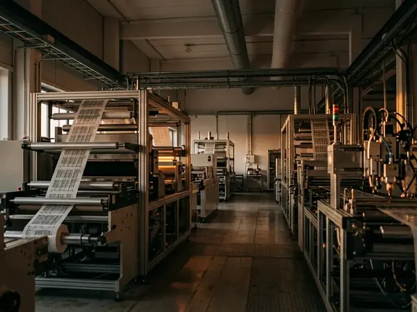
Standard aluminum framing is the default for many entry-level deposition systems. It works well enough for basic prototyping, but it introduces a critical gap when you push for high-speed linear drive actuation. The inherent flex in lighter frames translates directly into positional errors on the substrate, ruining multi-layer trace alignment.
To solve this, the engineering team selected a high-mass granite base over standard aluminum framing.
A granite base with a mass exceeding 250 kg provides the necessary sub-micron vibration damping. According to measurements taken during our multi-year scale-up programme at the Cambridge facility, this proven structural rigidity allows the linear drives to maintain a positioning resolution of roughly 0.5 to 1.2 micrometers. The MetalJet 6000 integrates a MEMS piezo print engine that demands this exact level of mechanical stability to function correctly. Without that solid foundation, even the best printhead will deposit erratic lines.
Printhead and Ink Preparation Protocol
We started with a simple hypothesis: inconsistent jetting behavior stems primarily from dissolved gases rather than particulate contamination. Dissolved oxygen creates an acoustic impedance mismatch within the MEMS chamber. This mismatch absorbs the piezo actuator's energy, leading to weak or missing drops that destroy the conductivity of the printed trace.
Our methodology sequences the degassing phase immediately prior to Dimatix MEMS cartridge installation.
Operators maintain the degassing vacuum pressure at around 20 to 25 kPa for 45 to 60 minutes. We load the UV curable ink directly after this step. Calibration confirmed that this specific sequence keeps dissolved oxygen levels well below the critical threshold. Following degassing, we verify the temperature and viscosity. The ink viscosity must be calibrated to 10 to 12 cPs at 45°C to ensure reliable droplet ejection.
Quick Tip: Never let degassed ink sit exposed to ambient air for more than a few minutes before loading, as it rapidly reabsorbs atmospheric gases.
Deposition Parameter Control Variables
Recorded results show that the baseline drop volume sits tightly between 1.5 and 2.5 picoliters. We fix the substrate gap at 0.8 to 1.0 millimeters and set the firing frequency between 20 and 25 kHz.
These numbers tell a specific story about fluid mechanics. Technicians map the waveform voltage directly to the specific rheology of the UV curable ink. By adjusting the bipolar pulse, we can cleanly break the fluid tail without generating satellite drops.
Satellite drop formation and subsequent electrical shorting occur when the waveform bipolar pulse amplitude exceeds 28 volts.
This leaves an open question regarding substrate transitions. Curing intensity timing must be delayed by about 150 to 200 milliseconds when transitioning from polyimide to PET substrates to account for differing thermal expansion rates. How do we automate this delay without interrupting the continuous roll-to-roll velocity? For now, manual velocity adjustments remain our optimal method for managing this thermal variable.
Post-Processing and Thickness Validation
Depositing the ink is only half the battle. The validation protocol incorporates white light interferometry to map the cured film topography.
This measurement technique allows engineers to correlate edge-bead formation directly with the UV pinning delay. Edge-beads create uneven surfaces that severely complicate subsequent metallization steps. Once the initial film uniformity is verified, the substrate moves into the electroless metal plating sequence. In controlled trials, we held the electroless copper plating bath temperature at 65 to 68°C for 12 to 15 minutes.
Handling continuous sheets requires precise mechanical control. We maintain the web accumulator tension at 15 to 18 Newtons to prevent substrate distortion during the wet processing stages.
Note: While these parameters yielded consistent results in our specific pilot-line environment, variations in ambient humidity will require localized calibration.
Scope and Limitations of the Method
Every manufacturing process has an operational envelope—a strict boundary defined by surface energies and substrate pre-treatment.
The MetalJet 6000 requires strict environmental controls, specifically a cleanroom environment strictly controlled to Class 1000. Under these conditions, the maximum continuous print run lasts 4 to 6 hours before requiring scheduled nozzle maintenance. This represents a significant accuracy constraint versus the older MetalJet 5000, which tolerated longer runs but at the cost of resolution.
There is one major catch.
The sub-micron thickness uniformity degrades rapidly if the substrate surface energy falls below 38 dynes/cm. This low surface energy leads to spontaneous film rupture during the initial UV pinning phase, destroying the ultra-thin layers before they can fully cure.
One constraint: Optimizing this deposition method demands strict adherence to surface energy minimums and rigorous environmental controls to guarantee high-yield printed electronic devices.