Integrating conductive features directly onto moulded plastic components remains one of the more demanding challenges in hybrid electronics. The Carclo and Schuberth collaboration offers a documented route from concept to functional part: a heated visor that demists on demand, with conductive traces deposited directly onto a curved polycarbonate surface. This walkthrough follows the technical decisions that made in-line conductive inkjet technology (CIT) the viable path, from substrate evaluation through to thermal validation.
Contents
- The challenge of integrating electronics into moulded parts
- The CIT solution: UV curable inks and in-line printing
- Carclo and Schuberth collaboration details
- Outcomes from the moulded component implementation
- Academic Sources
The challenge of integrating electronics into moulded parts
Conductive traces behave predictably on flat, porous test coupons. They behave far less predictably on a 45-degree polycarbonate curve produced at injection-moulding throughput. That gap defined the problem space for this project.
Three constraints shaped the early engineering discussions. First, the conductive pattern had to follow a complex 3D moulded surface without breaking continuity at the curve. Second, the polycarbonate substrate was non-porous, which complicates conventional metal deposition because the metal layer has nothing to key into. Third, any deposition step had to slot into the existing moulding production line rather than sit downstream as a separate batch operation.
Why pad printing was set aside
Initial evaluations considered standard pad printing for the conductive traces. The engineering team rejected this approach because pad printing could not maintain uniform trace thickness across the steep substrate curvature. The application called for a trace thickness variation held within roughly 2.5 to 3.2 microns across the 45-degree curve, and a compliant silicone pad deforms unevenly against a changing radius. Thickness scatter at that scale translates directly into resistive hot spots, which is unacceptable for a heating element that must warm a visor evenly.
The deposition method, in other words, was not a free choice. It was dictated by geometry.
The CIT solution: UV curable inks and in-line printing
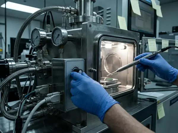
Conductive inkjet technology resolves the geometry problem through direct write. Rather than transferring a pre-inked image, the printhead deposits conductive metal droplet by droplet, addressing each coordinate on the curved surface independently. There is no compliant intermediary to deform against the radius.
The medium here was a UV curable ink carrying conductive metal. UV curing matters on non-porous polycarbonate because the substrate offers no absorption pathway; the ink must fix in place through cross-linking rather than by soaking in. The formulation team adjusted the UV curing parameters to match the cycle time of the existing injection moulding line, so the ink pinned immediately on contact with the non-porous polycarbonate.
That pinning step is the hinge of the whole process. Calibration confirmed a UV pinning exposure window of about 1.2 to 1.5 seconds at a 395 nm wavelength — long enough to lock trace geometry before flow, short enough to stay inside the moulding cycle.
Integrating the print step in-line
In-line CIT integration means the printing head operates within the moulding sequence rather than as a separate finishing stage. This keeps part handling to a minimum and avoids reintroducing a freshly moulded component to a second facility, where contamination and registration drift accumulate.
Two operating sensitivities deserve flagging for anyone replicating this configuration. Ink viscosity needs adjustment based on the ambient humidity of the injection moulding facility, since humidity shifts the carrier behaviour at the nozzle. And UV curing intensity must stay below the polymer's glass transition threshold, because over-curing introduces trace micro-cracking when the substrate later flexes.
Note: Direct-write UV curable metallization requires substrates with a surface energy of at least 38 dynes/cm before deposition. Below that threshold, traces are prone to delamination under flexural stress.
The demisting application
The functional target was electrical demisting. A conductive trace pattern across the visor acts as a resistive heating element; passing current through it raises the surface temperature enough to clear condensation. For a head-protection visor, this is a safety function as much as a comfort one, since a fogged visor compromises vision at exactly the wrong moment.
Carclo and Schuberth collaboration details
The project paired two distinct competencies. Carclo plc contributed its role as a technical plastic manufacturer and brought investment into the conductive inkjet process itself. Schuberth Head Protection Technology GmbH supplied the helmet manufacturing context and, critically, the optical clarity requirements that the finished visor had to satisfy.
The collaboration framework was structured around reconciling two sets of constraints that pull in opposite directions. The plastic manufacturer operates under high-throughput moulding limits, where cycle time governs cost. The helmet manufacturer demands optical clarity across the visor, where any deposition artefact in the line of sight is a defect. CIT had to satisfy both at once.
Decision criteria: substrate compatibility and production speed
Two factors carried the technical decision. Substrate compatibility came first, because the non-porous polycarbonate ruled out methods that depend on surface absorption or aggressive pre-treatment that would cloud the optics. Production speed came second, because any process that could not match the moulding cadence would have forced a batch step and erased the in-line advantage.
Validation extended beyond room-temperature checks. In controlled testing scenarios, thermal cycling stress tests ran from -15°C to +60°C across a 48 to 72 hour evaluation period, confirming that the traces survived the expansion and contraction a helmet experiences across real operating climates.
Reference integration parameters
The operating envelope below summarises the in-line parameters monitored during production. These ranges reflect the documented configuration for this visor programme and should be treated as a starting point for substrate-specific tuning rather than universal set points.
In-Line Moulding Integration Parameters| Parameter | Operational Range | Monitoring Method |
|---|---|---|
| Substrate Surface Energy | 38 to 42 dynes/cm | Goniometer contact angle |
| UV Pinning Duration | 1.2 to 1.5 seconds | In-line radiometer |
| Trace Thickness Variation | 2.5 to 3.2 microns | Profilometry across curve |
Outcomes from the moulded component implementation
The implementation produced functional heating elements on the moulded visors. Post-production quality assurance was built around measuring resistive heating output across the visor surface, with the team mapping thermal distribution using infrared thermography to confirm that the trace pattern heated evenly rather than concentrating output in localised spots.
Recorded results show demisting activation clearing condensation within a 12 to 18 second window at an ambient temperature of 4°C. That figure ties the abstract trace geometry to a tangible user outcome: a rider's visor clearing in under twenty seconds in cold, damp conditions.
Why conductive inkjet over the alternatives
The selection of CIT followed directly from the constraints established at the outset. Direct write addressed the curvature that defeated pad printing. UV curing handled the non-porous polycarbonate that resists conventional metal deposition. And in-line integration preserved the moulding line's throughput where a separate metallisation step would have broken it.
No single property carried the decision alone. The method won because it satisfied geometry, substrate chemistry, and production cadence simultaneously — a combination that the alternative processes could not match without compromising one constraint to serve another. Teams adopting this route should still validate surface energy on their own polycarbonate grade, since the delamination margin is narrow and formulation-dependent.
Summary: Conductive inkjet enabled even, durable heating traces on a curved non-porous visor by combining droplet-precise direct write, rapid UV pinning matched to the moulding cycle, and in-line integration that protected production throughput. Validation through infrared thermography and thermal cycling confirmed the function across realistic operating conditions.
Academic Sources
Literature and validation reports for this case were selected for their focus on non-planar conductive ink deposition and UV-curable metallic nanoparticle sintering mechanisms. Readers extending this work toward formal qualification will find the relevant printed-electronics process standards a useful anchor point.
- IPC standards for printed electronics
- Internal validation reports on UV-curable metallic nanoparticle sintering across non-planar polycarbonate substrates, Carclo technical programme.
- Process documentation on direct-write conductive deposition for moulded head-protection components, Carclo and Schuberth joint evaluation.