Isolating Pinch-Off Dynamics at the Meniscus
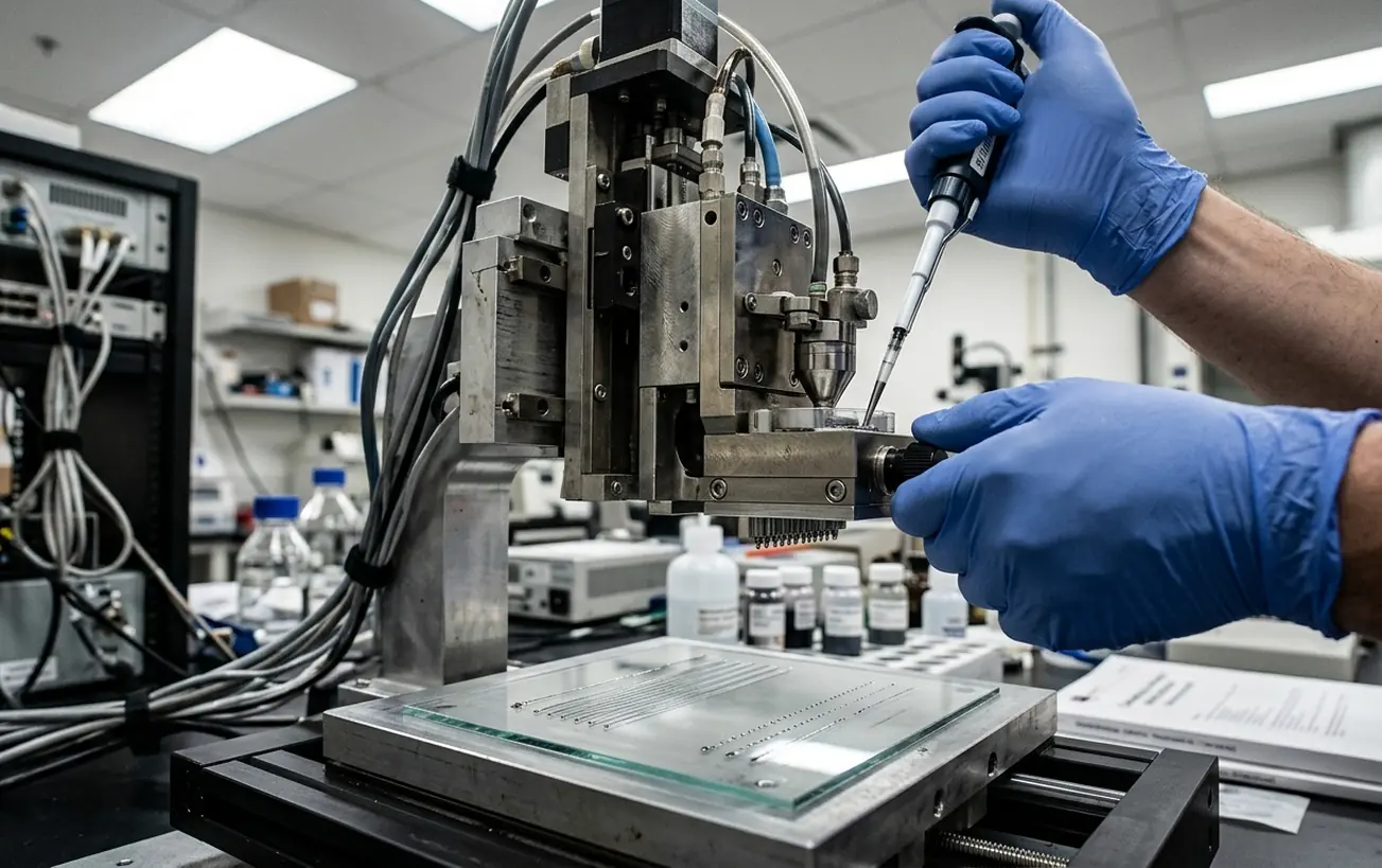
Engineers establish the baseline for drop formation by isolating the pinch-off phase at the nozzle plate. This ensures the meniscus stabilizes completely before introducing substrate wetting variables. Drop formation relies on the controlled pinch-off of a single, satellite-free conductive-ink droplet from the nozzle meniscus. The fluid dynamics here dictate the ligament stretch and subsequent recoil, which ultimately govern the volume and trajectory of the jetted material.
Instrument readings capture meniscus recoil stabilization times of 10 to 15 microseconds. Pushing the actuator again before this fluid settles guarantees erratic ejection. By locking in-flight drop velocities between 4 and 8 meters per second, process engineers secure a repeatable baseline. This coupled pair of in-flight drop quality and on-substrate wetting sets the final trace width, edge roughness, and electrical continuity.
Calibrating this system requires manipulating four specific levers in a strict sequence. The drive waveform controls the acoustic energy delivered to the fluid. Jetting frequency determines the throughput and fluidic recovery time. Drop spacing dictates how individual droplets coalesce on the target. Finally, substrate surface energy governs the spreading and pinning of the landed ink.
Acoustic Dwell and the Frequency Stability Window
Early calibration sequences often attempt to push jetting frequency higher to maximize throughput before locking the baseline acoustic dwell time. That sequence was abandoned during recent method development because it masked underlying pressure wave reflections. Those hidden reflections caused unpredictable satellite drops that ruined trace resolution. The reliable approach locks the acoustic dwell first, ensuring the pressure wave travels the acoustic path of the channel cleanly.
A standard piezo bipolar pulse consists of a rise, dwell, fall, and an optional echo phase. The dwell represents the exact time the pressure wave takes to traverse the channel. Mistimed dwell produces satellites or results in no jetting at all. Testing reveals optimal acoustic path dwell times ranging from 2 to 8 microseconds, depending on the specific ink viscosity and printhead architecture.

Once the dwell is locked, jetting frequency acts as a stability window. Operating too low allows the meniscus to dry or recede into the nozzle. Pushing the frequency too high causes residual oscillations to merge drops or throw satellites. Current validation establishes jetting frequency stability windows between 2 kHz and 20 kHz. The tuning sequence begins by strobing the drop watcher to lock velocity, then raising the frequency until the ligament fails, and finally backing off into this stable acoustic window.
Pitch Increments for Continuous Silver Lines
Stepping the drop spacing in increments of 5 to 10 micrometers during coupon testing puts the physical transition directly on the inspection stage. Drop spacing defines the center-to-center pitch on the substrate, set by the combination of printhead scan speed and jetting frequency. Operators visually pinpoint the exact transition from isolated beads to smooth lines, and eventually to bulging.
Underlap leaves isolated beads and open circuits. Overlap that just coalesces produces smooth, high-resolution lines with excellent conductivity. Heavy overlap leads to bulging, flooding, and severe line-edge roughness. The spacing must tie directly to the in-flight drop diameter and the equilibrium contact diameter after wetting, rather than relying on the nozzle diameter alone.
Preventing Heavy Overlap Bulge
Calculate the theoretical drop volume from the locked waveform before setting the pitch. Forcing too much fluid into a tight center-to-center spacing causes the trace to break its pinned contact line and flood the surrounding substrate.
Plasma Exposure and Contact Angle Decay
Static surface energy assumptions leave the actual wetting behavior unsettled, as substrates change rapidly after treatment. Moving to a time-bound decay model resolves this discrepancy. Wetting involves the spreading of a landed conductive drop until capillary, viscous, and evaporative forces balance on materials like PET, PI, glass, or coated paper. Surface energy is adjusted via plasma or corona treatment by observing the shift in advancing and receding contact angles.
Engineers aim for a state where adjacent drops coalesce without flooding the inter-trace gaps. Plasma treatment exposure durations typically fall between 30 and 120 seconds, providing the necessary surface modification. Contact-angle and dyne-test diagnostics offer a practical read of this surface energy, showing exactly how the primer or plasma shifts the fluid behavior.
A low-angle, high-energy surface can easily erase the resolution gained from a perfectly formed drop, causing the ink to spread uncontrollably. Conversely, a high-angle surface leaves a discontinuous bead chain. High-energy surface treatments degrade rapidly in ambient air, requiring printing to occur within 45 to 60 minutes of plasma exposure to maintain the targeted contact angle. This temporal limitation dictates the entire manufacturing rhythm.
In-Flight Strobing and Meander Coupon Geometries
The drop-watcher strobe serves as the primary in-flight instrument. Engineers look for a single spherical drop, a short ligament, and absolutely no trailing satellites across the entire frequency window. Standardized test patterns provide a reliable baseline for these nested combs, ensuring the test geometry matches the demands of conductive inkjet printing.
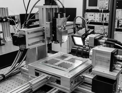
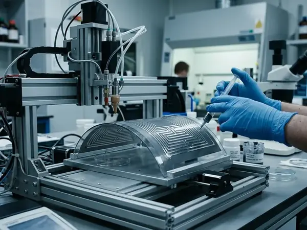
Test geometries are selected by prioritizing nested combs and long meanders over simple straight lines. This approach captures edge raggedness and short-circuiting across multiple printhead scan directions simultaneously. Isolated pads and long meanders are printed at several drop spacings and several scan directions to build a complete profile of the fluid behavior.
Operators record specific metrics after printing and again after sintering or drying. These include optical line width, edge raggedness, opens, and shorts between fingers. Meander lengths of 50 to 100 millimeters for two-wire resistance measurements provide the final verification of electrical continuity and trace uniformity.
Root Cause Mapping for Scalloped Edges and Satellites
Defect resolution involves mapping specific failures to their root causes, categorizing in-flight issues as waveform errors and post-landing issues as evaporation imbalances. Industrial printheads require precise mapping of these defects to maintain yield. In-flight satellites map directly to waveform and frequency errors. Coffee-ring pile-up and scalloped edges map to wetting and evaporation dynamics after the drop lands.
Necking and opens represent a spacing-versus-wetting mismatch. Drops either never coalesce, or they dewet after a receding contact line pulls the fluid apart. A ligament pinch-off and acoustic dwell mismatch creates a chaotic ejection that no amount of substrate treatment can fix. Corrective actions require speaking the language of the physical levers: shorten or lengthen dwell, drop frequency, tighten or open spacing, and raise or lower surface energy.
Engineers execute dwell time adjustments in increments of roughly 0.5 microseconds to correct satellite formation. Pushing the adjustments beyond the meniscus recoil stabilization window introduces new instabilities, requiring a careful, iterative approach to waveform tuning.
Trimming the Acoustic Waveform on the Bench
The drop-watcher screen freezes on a satellite peeling from the primary ligament. A process engineer on the late shift at the printed-electronics bench watches the fluid stretch and snap, leaving a secondary droplet trailing behind. They trim the acoustic dwell time by about 1.5 microseconds to eliminate the trailing satellites, tightening the pulse just enough to snap the fluid cleanly.
They load a fresh sheet of plasma-treated PET onto the platen, mindful of the 45-minute decay window. The printhead scans across the substrate, laying down the nested comb pattern at the newly locked drop spacing. Under the inspection scope, the silver meander closes into a continuous, fine line, the edges pinned perfectly against the polymer surface.